A Couple of Ideas Jewelers Might Find Helpful

March 2nd, 2012


As an artist, many years ago I used to also build jewelry as part of my living but have spent most of my recent years printmaking and teaching at a university. I had a well-equipped shop doing constructed and centrifugal lost wax casting; working in both gold and sterling on commissioned piece - as well as selling through some outlets across Canada. Luxury taxes made jewelry not as profitable as commercial art so I after a number of years stopped serious jewelry manufacturing and turned to printmaking and teaching.

As I am now very old, I would like to pass on two simple modifications of common tools we all use, which has made working on a piece easier and less frustrating. I have followed the jewelry forum with great interest, as well as looked what equipment is for sale to the craftsmen, to see nothing like my simple innovations.

When I started to work in titanium, I found its’ two main characteristics to be overlooked for use in making a pair of self-closing tweezers. The high melting temperature of the metal and the fact it is a very poor heat conductor make this possible. By using appropriate length of suitable spring steel to supply the power for the closure, two pieces of titanium can be pop riveted to produce tweezers such as these.

72 DSCN090272 DSCN090772 DSCN0905

I am sure you could spend more time and do a better job than I did on the two shown, but they were assembled in a hurry at different times; when the first thinner prototype set was mislaid. The working principal is to set a fulcrum point (lines) somewhere in the middle of the tweezers so that pressure on the spring section would force the titanium points apart. One doesn’t need much pressure as they are meant to hold pieces of solder while tipping the claws holding a diamond - or critical joints where heat dissipation and fear of tweezers soldering together is avoided.

I also use a sharp titanium or tungsten point to push solder around.

72 peg 372 peg 172 peg 2

Beside the regular V slotted board for sawing, I have been using tapered wooden table legs to make special filing bench boards. A slight tapper will allow you to turn the peg into any ordination suited best for filing at that time. I have a large selection of pegs that I even change shape to better accommodate the work.

I have been included in major shows in those years, even won DeBeers Diamond major award in 1977. You can see pictures of some work that I had time to photograph in those busy days on my blog at: http://www.ndiprintmaking.ca/jewelry.html. Since I have the tools, metal and skill, I do sometimes build pieces for members in my family.

Nik Semenoff D. Litt

So You Don’t Have a Press

January 20th, 2012

New printing press are expensive and used one sell for top dollars as they are quickly bought up by a practicing printer looking for one. Students that graduate with printmaking in mind, find few opportunities in most centers; like a cooperative studio in which they can use the equipment on a payment of membership. Only one of my printmaking students has continued printmaking because I was able to help him build both a litho and later an etching press. One of my better print students has stopped doing art for the lack of a press, which he told me when I met him on one of his delivery routes working for a small company. If only these students could continue printmaking until they somehow can make connections with a press, their spirits would keep the dream alive and to keep looking instead of giving up. It was this reason that I developed a unit consisting of seven ball bearings assembled on two shafts with alternating tracks covering a total of three inches width. It was intended for printing waterless lithography, but has been accepted mostly by monoprinters.

Because of the small area making contact of the seven
bearings unto the plate surface, the pressure can be
between 800-1050 psi, depending on ones strength and
position above the plate. This seems to be sufficient for
properly dampened rag paper.

Sometime ago, a European printmaker (Ad Stijnman) contacted me about pictures of Sashas’ Palm Press to include in a paper dealing with intaglio. He told me it has been successfully used to print etching plates, which surprised me as I had never considered there would be enough pressure for successful prints. As I have never printed an etching edition in my life – only did research into a safer mordant – so I decided to do some research.

I had given away an old small etching press years ago to a student when I built my own 15 inch wide convertible etching/lithography press; which I have recently sold because there seemed no need for an etching press after my work in 2008 on the cupric chloride mordant to etch copper plates. I had a bunch of proofs from my early research using plates I had made using various techniques. I started to print these plates using Daniel Smith etching ink and a palm press, using a soft orange felt-like chamois matting made in Germany, which acted both as a sizing catcher and felt blanket.

I found that the ink had to be softer so added Easy Wipe. To start the research, I chose to use cheaper cover stock instead of thicker harder rag paper. Soaking and surface drying the sheets was done as normal, but using other two large piece of the German synthetic “Chamois” and a rolling pin. By adjusting the ink viscosity and wiping techniques, I was able to get decent prints but felt things could be made much easier.

Years ago I had worked with Alan Flint into making one’s own waterbased ink by using Lascaux clear screen base and dry pigments. This ink was easy to grind with a spatula and could keep in a plastic jar for years without forming a skin on the top. It tended to dry faster than oil based ink, so a bit of acrylic retarder would give me (and some special students) more time to wipe the plate cleanly and for the creation of plate tone if that was required. I had some of this old ink on hand from that research so decided that a waterbased ink would be the direction to go because the damp paper should absorb the ink better than an oily one. As I used up the small amount I had, I decided to see if Hunts or Golden screen base would work as well when ground with Mars black or lampblack. They all seemed to work well enough that in the end I mixed the three versions together into one jar.

Because some etchers have been using Daniel Smith waterbased relief ink for their etching plates, I decided to try that route as well since I had a range of these DS relief ink. I found them too stiff and so modified it with Lascaux clear base to get the proper viscosity.

Being a heretic amongst etchers, I have been using tulle instead of tarlatan for wiping the plates. This works just as well and can be washed clean in soapy water.

The amount of soaking of the paper became a bit of an issue with the water soluble ink; since it could penetrate deeper and produce a wider darker line than intended. Still experimenting with cheaper cover stock, I found a technique that worked well with the palm press, so decided if the use of bottle bottoms would work here as well as it had in my research into printing waterless lithographs. I had experimented with three different sized bottles, eventually deciding that the largest and smallest where all I needed.

bottles ssmall bottle sDSCN0865

The large baby food bottle was attached to the wood by means of screws from inside the metal lid, then the bottle was put into the top. The smaller bottle was quite tall so I snapped off the opening and glued it into the hole I drill in the piece of wood.

By adding a wider piece of wood on top as a handle, more pressure could be applied without hurting my palm and fingers. The smaller bottle has small bumps that greatly increases the pressure on an area to get the paper pushed deeper into the lines. To prevent damage to the damp paper and allow the bottle to slide easily over the surface, I chose a sheet of thinner frosted Mylar that was meant for use with CAD printers. It is ¼ thinner and should not spread the pressure over a larger area and therefor have a greater effect.

It was now time to try proper rag paper to see if professional prints could be made. I found that plain soaking of the sheets did not produce the quality I wanted because too little soaking left the fibers hard and poor pickup of ink. Too long and the simple pressing of the sheet between blotting material, left too much water within the fibers so the ink could come completely through the to the back; with the image becoming too dark as the ink migrated sideways as well. On a regular etching press, the sizing catcher and felt would absorb excess water but the Mylar could not – just squeezed it out.

nude s ragfish s 001fly 001s

Some of the other plates that I printed with a bottle and dampened rag paper. The nude is 4.25 X 5 inches, the fish 6 X 7.5 inches and the fly 4 X 5.5 inches.

To make the Mylar surface more slippery, I used the “Johnny Wax” that I have developed to replace common grease on a litho press tympan. The Mylar is much larger than the paper and stays in place when the bottle is rubbed across it in many directions. I usually start by going in a circle at the center of the plate, working out until I could feel the edge of the metal. For aquatints and darker areas, the smaller bottle can be used to make sure the paper has been pressed down into the deeper recesses and pull out the ink. One can carefully lift one corner of the paper to see how well the ink has taken and put it back to apply more pressure if needed. It is important to go over the entire surface carefully without leaving any area weak from ink.

man 001sfeather 001sbook 001s

These three prints were made with waterbased ink and either large or small bottle bottoms. The first print is a (9.5 X 7 inch) solarplate that was made for me by Dan Welden for him to see how toner images on Mylar would work with his plates. Actual printing time: 39 seconds.

The middle print (8 X 11.5 inch) is an aquatint on aluminium using copper sulfate as a mordant. Actual printing time: 59 seconds

The last is an electro-etched zinc plate (5 X3.5 inch) using Riston film for exposure to a toner wash on Mylar and a small Xerox copy of a book. These prints are on Stonehenge rag paper. Actual print time: 37 seconds

Because I no longer manufacture palm presses, there was no point of showing prints using that method - since the bottle works just about as well, it should be possible for more etchers to use this process.

What was required was the older method of preparing paper for printing by wetting every second sheet into a stack that was then wrapped in plastic and pressed between flat surfaces, by placing a weight on the top - thus letting the water content to even out overnight. The sheet was now limp and just damp with no free water on the surface. Now the rag paper produced even better prints than the cover stock, which was soaked for a shorter time and at uneven intervals.

I noticed on the Internet that there are many etchers who do not produce large sized prints and this might make many of them happy to print with this method. With the new waterbased etching ink on the market, you should find one suitable that works; if you don’t care to make your own, as some printers still do, using lampblack and plate oil varnish.

I have uploaded two interesting videos to You Tube; one on this process and the other a more detailed teaching event showing steps of my waterless litho  process. The easiest way to find them in to go to You Tube and use my name as the tag, which will target these videos and disregard other tags that will complicate the search. I now realize the text passages are too short, but using the space bar, you can pause the video and read a leisure.

Instead of reediting the pieces, I would rather take the time to do more on some techniques that will help make printing easier.

Making an Etching Press with Jacob Semko

March 25th, 2011


Planning Making the Press

The concept of using only metal where the pressure needed, can help it easier and cheaper to
make presses. My small press is convertible to either etching or lithography – even having linear offset system for litho. My press is much more complicated to build and uses a drive motor.

After working on his litho press with me, Jacob decided that he would like a large etching press for etchings as well as relief prints. We talked it over to decide the size and other features he wanted included. Since I had made a smaller convertible for my daughter who as teaching art at the time, it was a proven concept that just needed to upsized. The principal of making just the pressure area from steel was accepted as Jacob had woodworking facilities at home to finish off the construction.
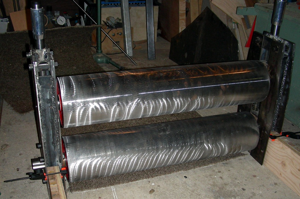
The Rollers

DSCN11302006-06-22_15-00-49DSCN11362006-06-22_15-04-29DSCN11442006-06-22_15-38-41
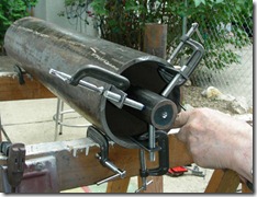
Cutting and trimming a large diameter steel tube is best done with an abrasive cutoff saw. My saw would not cut all the way through, so the tube was rotated to cut sections at a time.

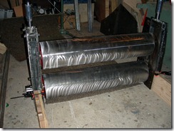
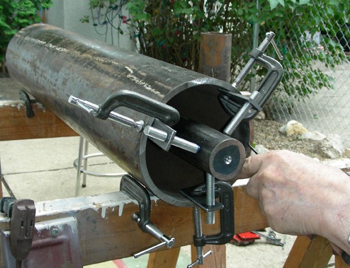
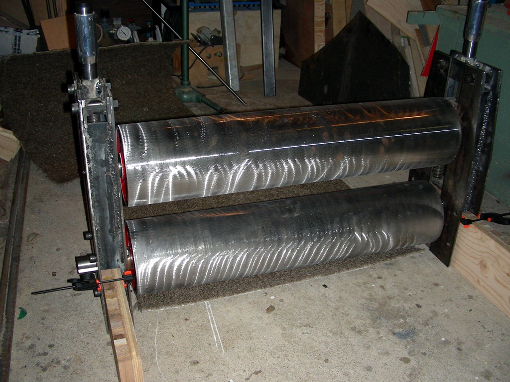
The first thing to consider was the two rollers, the possible diameter and method of construction. As there are two scrap metal yards in the city, we went to them to see what kind of steel tubing was available. We found suitable 3/8th inch thick steel tubing that was 6 inches in diameter; for two lengths to make a 30 inch wide bed. The first thing to do was to cut the tubes to size - using a cutoff disc. The tube where then trimmed to length, leaving a little for final truing on a lathe.

It was decided that we would use a high quality shaft as the Brandt press at the university had broken when a student had put too much pressure on the rollers. When I went to my friend who owned a machine shop, he came to look at the damage and told me the steel was likely a number XXXX which should have been YYYY, that he had in his shop. I told him that the outside tube might be supported with a doughnut-like ring inside, which would make it impossible for him to replace the shaft. We took off the roller and in week or so, called me that it was fixed with the better steel shaft and a trued new surface on a lathe.

DSCN11602006-06-23_15-29-06DSCN11712006-07-03_13-05-11DSCN11762006-07-03_14-20-57
The steel had to be cut in straight lines, then trimmed to fit unto the wooden support screwed to a faceplate. The center of the intended disc was first placed touching the point of the tailstock, then four screws were set into place. A hole was drilled and expanded with a boring tool to fit the diameter of the shaft.

We decided to reinforce the tube from the inside with doughnut rings, so the 1/4 inch sheet steel from the scrap yard was sectioned to make six rings - one on the inside of each and two for the ends. The cutoff saw was used to separate the pieces and trim them closer to a circle. The best way we thought of making the donuts was to cut out a plywood disc and screw it unto the faceplate of the lathe. Four holes to screw the sheets unto the plywood on the faceplate was all that was needed to produce center hole that was made to fit the shaft, using a boring tool.

DSCN12162006-07-13_14-56-45

The plates were  transferred to a three jaw chuck to lathe the outer edge that would fit inside the roller tube. You will notice that I have made a more solid tool holder as I had found the original tool post was not really ridged enough, which I only use when needed for angle cuts. The block will take both 1/4 and 1/2 inch bits, considering the project.


Roller Assembly

DSCN12212006-07-17_14-15-22
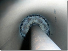
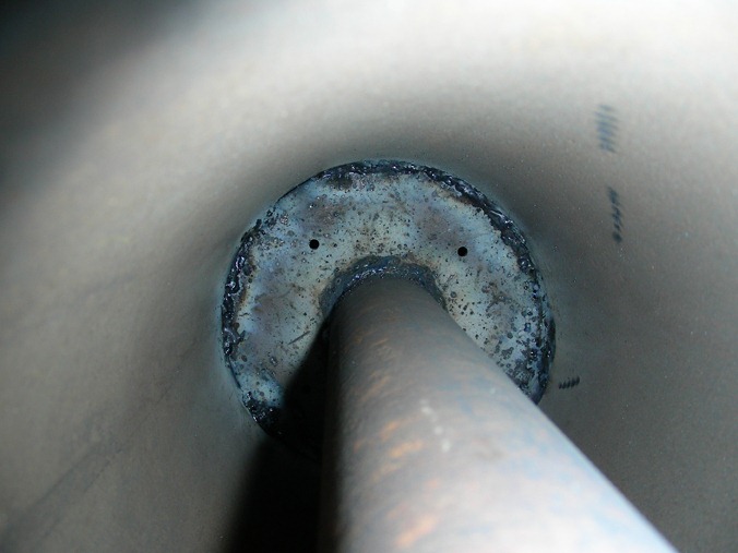
The discs fit the inside with little room to spare because of the welded seam produced in the manufacturing of steel pipe. The shaft was one of the most expensive part of the press because of special features needed to prevent it breaking.
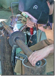
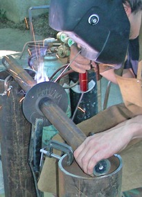
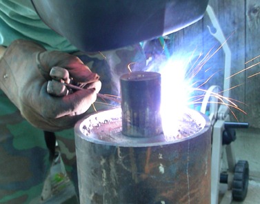
Since it was summer and nice outside, we decided to move welding outdoors since I could easily get power to the 110 VAC arc welder from a power plug near the basement window. Since the chosen steel could become brittle from arc welding and extreme local heating, we used an acetylene torch to preheat the shaft before arcing the ring into place.

 
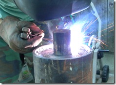
After drilling centers on the shaft, we were prepared to weld the pieces together. Jacob did most of the welding, using my underpowered 110 VAC unit that was allowed in residential areas.

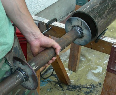
With the center support and one end welded to the shaft, it was inserted into the tube and centered with three improvised threaded rods clamped to the tube edge. The other end was shimmed to place the shaft perfectly in the center and then welded into place. The clamping support was removed and the center ring was welded to the tube by holding the welding rods vertically. Now the other end ring could be used to close up the end by again using small shims to get it as perfect as possible.

    DSCN12632006-07-22_16-05-27DSCN12742006-07-23_15-25-48 
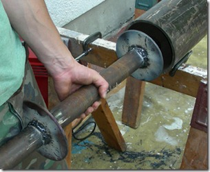
Using disc grinders and round grinding points, the rough but still strong welds were smoothed out.

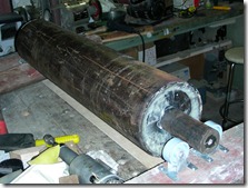
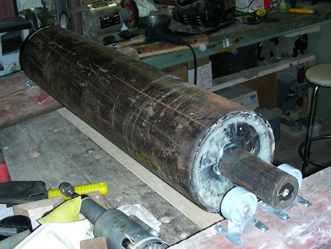
Since my small 110 volt welder was inadequate for thick metal, the welds are not cosmetic but strong enough for the stress. Some grinding and filling with body putty made a decent looking set of rollers. One of the shafts is longer at one end to accommodate the gear to turn the bottom drive roller.

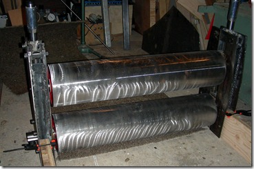
Since my lathe was too short for this set of rollers, we took them to an industrial metal shop that  trued the surfaces and shaft ends cut to size. As they didn’t seem to have a belt sander on hand, they used a disc sander that produced the unsightly surface.


Bearings

DSCN0332One could use ball or roller bearings, but to keep costs down, we used the bushing system similar to what I used on my convertible press. It was more work but a learning experience for us as well. We decided to use two inch long bushing that set the dimensions of many other parts, like the upright supports and wooden sides of the press.

DSCN1385DSCN1496DSCN1925
Welding the boxes needed to support the bronze bearing, which are more than good enough for slow turning and the pressure needed for printing an etching. The heavy support of the bearing was need for Jacobs press as I did not use that feature with my smaller rollers.

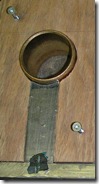
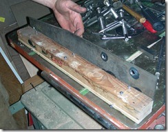
The first thing was to make metal boxes with support for the Oilite bronze bushing. The sides were made from 2" wide steel 1/4" thick, while the end taking pressure was 1/2 inch. The piece were welded together using magnetic holders to get perfect square units. Sheets were cut to fit inside the boxes and welded into place from the inside. A thicker piece of steel was cut to length and one end ground with an inside curve that fits the bushing diameter.

       DSCN1910         DSCN1923
My lathe does not have an indexing feature, so to hold the chuck solid, I used two clamps.
The hand grinder has a attachment for use on a lathe, making it possible for us to grind a curve.

There would be hardwood filling the space with the grain running horizontal to accommodate any side pressure put on the bushing; this was done by gluing two pieces of oak at 90′ to each other to get the required thickness for the box. The piece of steel that was ground to the curve of the bushing was welded into place - after the hole to accept the shaft for the drive gear was made by drilling and filing smooth. The other three bushings did not need this effort.

       DSCN1931DSCN1944 DSCN2244
Much fitting and adaption of materials was necessary to get the bearing strong enough for a press.

The wood pieces were fitted as close as possible by using temporary screws to put out the sections as we worked. Epoxy was used to glue the wood and metal box together - but it was necessary to keep the epoxy from flowing into the interior of the bushing by using a paper tube lathed to size and pushing it tightly against the metal backing. Grease nipples were added after drilling through the wood and the bushing, for future lubricating of the press.

 DSCN1886DSCN1893DSCN1890DSCN1899
Construction of the bushing holder seems complicated, but it would be nearly as complicated to use commercial ball bearing as done on manufactured presses. All dimensions would be different.

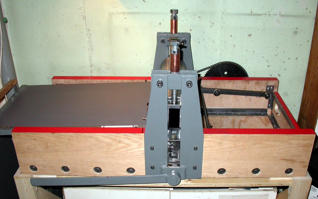
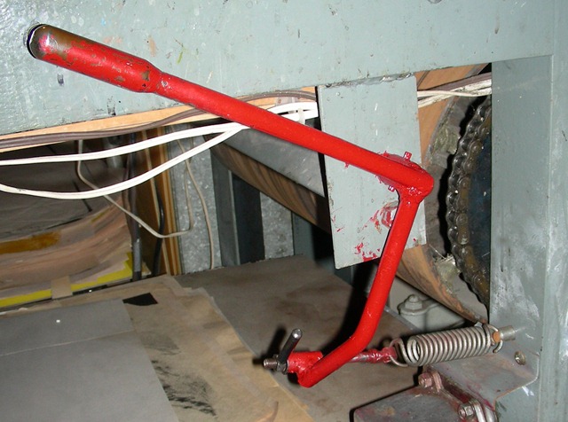
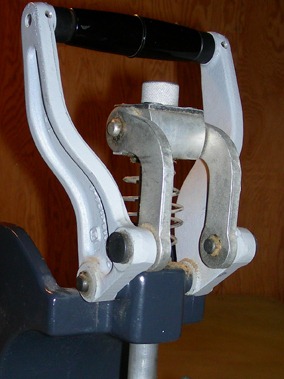
Holes had been drilled at the ends that held short rods unto which strong spring were used to keep the rollers apart. You will notice the different lengths of the boxes that give us space to keep the drive roller off the bottom of the completed press. The top roller bushing needed a ring to hold the threaded rod that is apply pressure. This was welded on and the sides ground off to the thickness of the box.

Frame Supports

    DSCN12822006-08-05_14-12-31DSCN12882006-08-05_15-28-01DSCN12922006-08-05_17-30-55
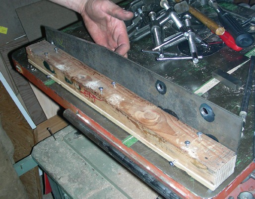
        Marking, drilling and cutting the angle for the taper at the top of the bearing supports.

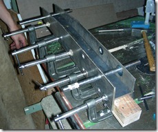
The framework to hold the bushings and pressure system were constructed from the 2" wide flat steel and also 3" wide material for the outside. The top was tapered by cutting off a piece 1 1/4" and 8 " long at one side. Holes were drilled for the bottom bushings and two more to connect to the wooden sides of the press. Holes at the tapered end were added to accept metal cross pieces holding the pressure screw and top cross bar

DSCN13042006-08-07_14-30-21
It is important to use jibs for assembling a number of similar pieces. It need not be complicated but well thought out by using common materials in the workshop.

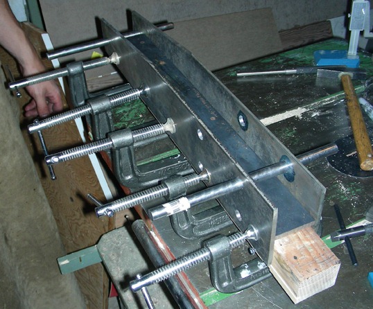
A jig was setup to make sure the supports were identical and accurately welded together. The basis for the jib was just a piece of scrap lumber planed to the width of two inches - the same the the bearing thickness. A series of screws keep the metal off the wood as the welding heat would burn the lumber. Rods were inserted into the holes where bolts go and the pieces adjusted to get perfect 90′ angle in all directions. Then they were welded together by first tacking the metal to prevent warping in the long weld.

        DSCN1950DSCN1961DSCN1966
Before drilling the holes into the bearings, we used a gauge on a machinist granite block to make sure the distance from the bottom was the same on both sides.

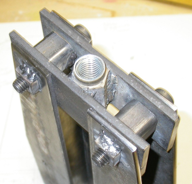
Holes were drilled in the bottom bushing and the supports temporarily bolted together to make and weld the upper assembly. It consisted of short joining flat metal and spacers to fit the 2" spacing set for the bushing boxes. Nuts were welded on one side of the supports to accept bolts that would tie the two side supports together.

DSCN1975DSCN2039
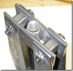
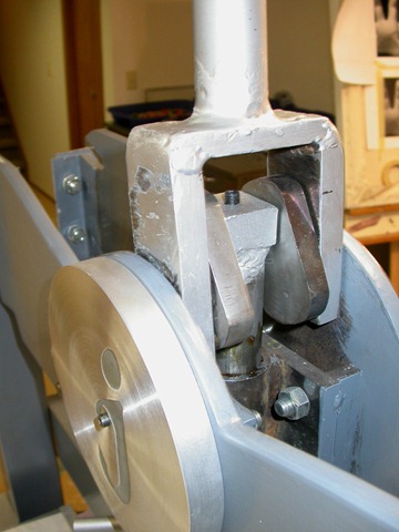
The coupling devises were fitted between the support, then lathed to accept the vernier column before welded in place. There may have been easier ways of doing this, but this worked out.

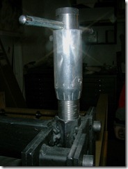
A threaded coupling "nut" was made wider by welding on pieces to opposite sides, then ground flat to fit nicely in between. One end was lathed circular to accept a piece of aluminium tubing that was engraved with spacing lines (more later) for setting pressure accurately.  This was done by putting in a short section of threaded rod into the lathe chuck and screwing the coupling unto it - making it perfectly centered. All parts welded together - as well as the spacers.

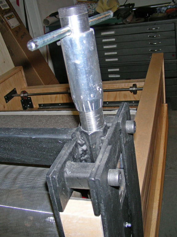
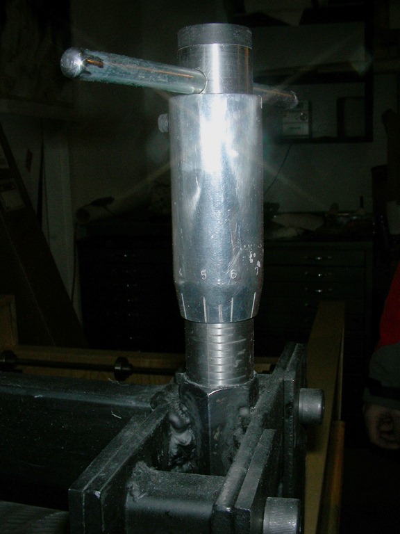
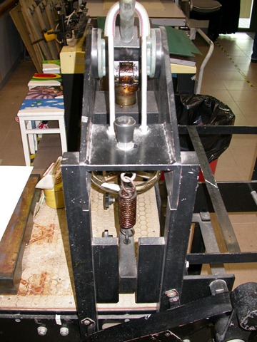
Vernier Pressure System

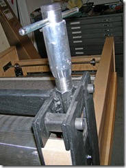
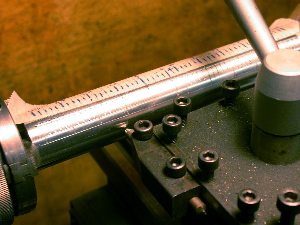
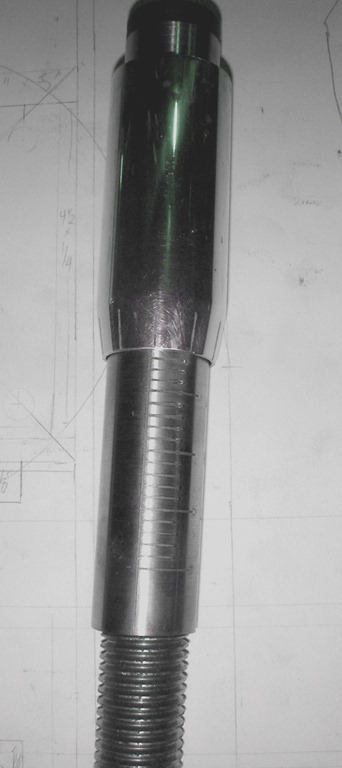
This was a luxury feature that is included in the better presses to make pressure setting accurately. It consisted of aluminium tubing that fit inside one another. The smaller pieces were lathed on the inside at one end to fit the top of the threaded coupling used to apply pressure. It was then engraved on the lathe by using a pointed tool for longitudinal “0” line and the shorter spacing lines.

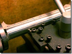
I used a small 3-jaw chuck from my Unimat to hold the tube between centers, using a larger bullnose at the tail stock. It was easy to make the long vertical line by working the tool along the lathe bed. The short lines were transferred from tape spacing by turning the chuck by hand, using the square handle that comes with chucks.


     DSCN2214DSCN2227DSCN2236
Using the lathe to make the division on the vernier was our way of producing the working system.

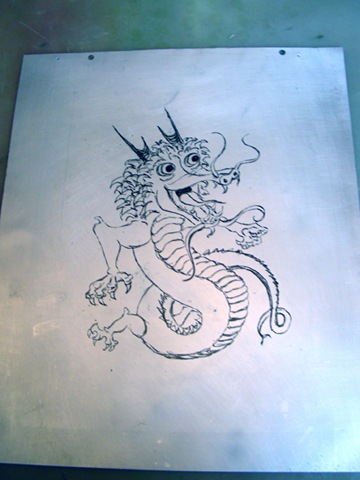
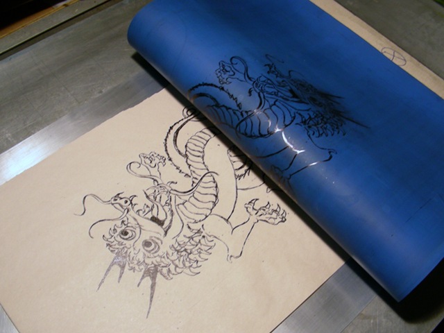
The finer increments allowed by the division of 360′ was done on the larger tube. One end was given a slight angle by setting the tool post to produce the short taper. A sheet of paper was produced with lines 36′ apart with a circle to make sure the tube is centered. A special small piece of metal, with an angle equal to the taper on the tube, was secured to a handle to make sure the line would be vertical. Then the soft ground was scratched with a needle and etched in copper sulfate mordant. Numbers were stamped above the lines with a standard set of punches.

   DSCN2253
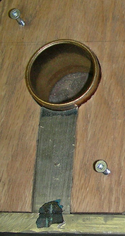
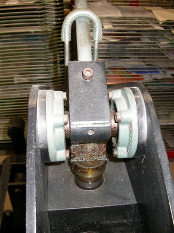
The components making up the vernier pressure system that was epoxied into place on the press.

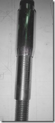
Two screws were put at the top to adjust the vernier for setting the zero point. The threaded rod was capped by lathing another coupling to fit the inside of the larger tube just finished. It was cut in half and screwed to one end of the heavy threaded rod. A hole was drilled through it and the rod for a short piece of thinner rod forced and glued into place to help adjustment. The two screws would grab unto this small section as it went down when turned; the graduation would be 1/10th the pitch of the treaded rod. Jacob topped it off with a piece of ebony lathed to fit.

Frame Assembly

DSCN1954DSCN1957

The assembly of the supporting frame and drive roller required some spacers, so Jacob used my rolling mill to produce shims that fit the exact thickness for each bolt. Holes were punched and the brass hammered flat to slide in. The cross piece connecting the two frames at the top was now cut to length from a piece of rectangular tubing and welded unto respective sections; ready to assemble the press. This was the distance set by the length of the rollers and bearings.

Adjustable Bed Support

DSCN2027DSCN2030DSCN2036
Making many fittings for the support of the press bed. Epoxy was easier than precision lathing.

What is usually used on presses is an offset method that adjusts a bearing or wheel to just hold up the bed evenly as it goes through the rollers. Short pieces of rod were cut and lathed at one end to fit the inside of ball bearings that we picked to act as wheels. They were then put into the lathe chuck with a piece of metal against one of the jaws to produce an off center hole to allow the adjustment needed. Two holes were drilled and taped to set the height of the wheels. The bearings were epoxied to the end and later put unto long rods that had flat pieces of iron welded at each end. These were dropped into holdup slots attached to the inside of the press walls. The total length was exactly the distance between the two wooden sides and screwed at a height that would allow for adjustment.

The Wooden Press Sides

    DSCN3071DSCN3073
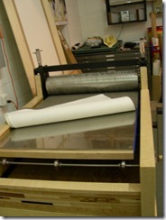
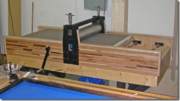
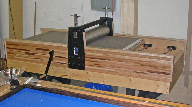
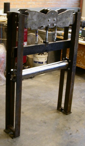
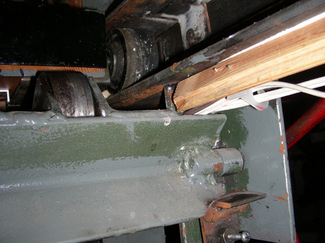
     The press in place at Jacobs’ first studio - and has been moved many times since being built.

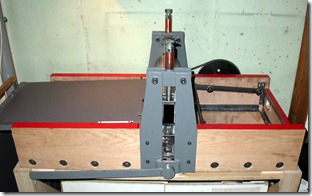
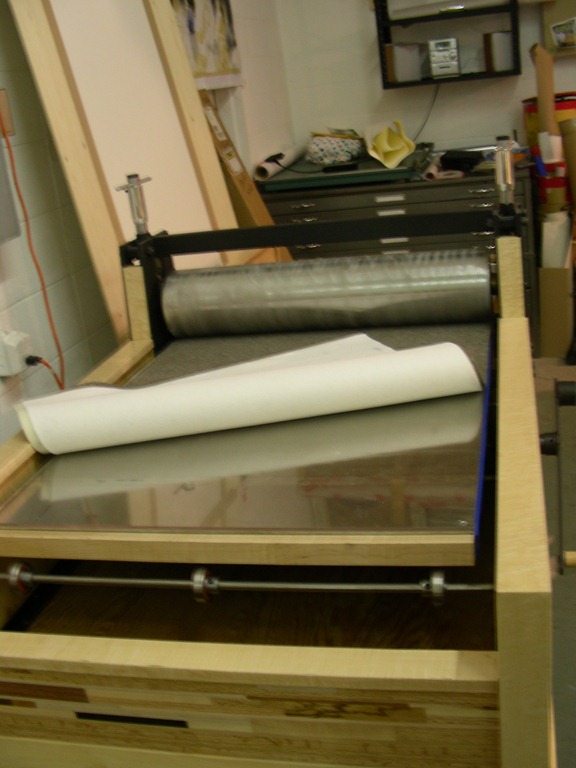
At this point Jacob took the rollers and frame home to work on the rest of the press. He used plywood unto which he assembled assorted hardwoods to produce an interesting surface. The press bed was made of hardwood unto which a 1/4” piece of aluminium was used for a perfectly flat surface. You can see the bed support wheels within the body of the press. Pillow blocks were added to transmit the handle energy to the opposite side of the press, where a simple reducing system of a chain drive was used. The bottom has become a storage space for blankets and such, holding quite a bit of material where it could be easily accessible.

I am sure Jacob and his father took some pictures on their work of building the wooden frame and assembling the final press, but I have never seen them. Since the woodworking is simpler in such a project, I feel there has been enough information given for some printers to take on building a press.

If there are any questions about some part of the project, please get back to me directly on my e-mail as the registration system has been dismantled because of spams etc. I will be posting an article on my small convertible press, which is much more complicated, having to employ an off/on pressure system required for scraper bar lithography.

Building your Own Press

July 5th, 2010
EPSON DSC picture

Early designs for litho presses as shown in De Capo Press reprint of Senefelder’s book

There have been questions on other forums asking for information on building ones’ own press - etching or litho. I have heard of printmakers designing and building their own press more directed to how they print - whether they printed privately or as collaborators. I have seen some very sophisticated litho presses doing the job just as well or maybe more effectively than from one of the major press manufacturers. One by a professional litho collaborator who made a very sophisticated press. Yes it can be done with a little help from your local machine shop and a bit of knowledge of metal work, welding and fabrication. Certainly at a fraction of commercial units.

Just like most printmakers, I did not have the funds for a commercial press - even at a second hand price. Being quite handy with tools and having a better workshop than most artists, I decided to build my own litho press in the mid 1980’s; but rethinking the use of a press to make one better. 

OLYMPUS DIGITAL CAMERA         Back in the 50’s, I had acquired a dozen small 12 x 10 inch stones from an old printing shop who were eager to get rid of them at a giveaway price, so I built my first press using the frame of a small letterpress for the moving bed and a screw down frame from an old copying squeeze-down press that many linocut printers still use for editions. With some  modifications, such as a scraper bar and pressure release system, I was able to master the diabolical craft of traditional lithography and produce small size prints. 


OLYMPUS DIGITAL CAMERA         old stone weed

A similar press was taken apart and modified to form the scraper bar system that allowed me to print stone lithos like the proof on the right.

As my life moved on with different priorities of a family, I more or less gave up lithography except for small art projects with my children. In 1982, I was invited to use the facilities at the University of Saskatchewan as I now on faculty in the college of Extension as a media specialist, involved in producing printed material. The marvel of drawing on a large stone rekindled my interest in lithography as I started to print editions in the print department.

I presume most printmaking departments are troubled with the same problem; careless students who seldom cleanup after printing their edition, leaving presses and area a disaster for anyone hoping to produce clean editions. Being given access to the facilities, I did not take advantage of being a faculty member, so allotted my time on the press to be the same as the students. But this became a problem as too much time was spent to clean the area if I wanted to end up with spotless prints. It was now time to think how I could produce a larger press to handle at least 22 x 30 inch sheets.


Hand printing takes tremendous pressure to get ink transferred to paper, but that only concerns the middle section of the common press - the rest of the unit is to support the moving press bed. The total space a press takes up consists of the middle transfer section and the ends to hold up the press bed as it passes under pressure. This is from Jacobl Semko’s litho press, using a 4 inch diameter steel roller made for us by a friendly machine shop who was interested in helping the students .

Common ball bearings were used in their presses, whereas I used bronze bushings supported in steel and resin casings.


OLYMPUS DIGITAL CAMERA

In litho presses, one side becomes more important as we print in one direction only - etchers can go both ways. So for a litho press, the working side is longer than the press bed, the section on the other side of the scraper bar can be considerably shorter; thus saving space in the studio. Unless one is printing on large stones, the weight of the press bed by itself can be carried by less robust metal work - even hardwood could do the job. This means one only has to be concerned with the main transfer system that contains rollers and an adjustable pressure system, plus a means to move the bed through without too much effort. In many ways an etching press is easier to construct as pressure is set by screws for the end bearings; the rest left to blankets. On my press, the total length is 74 inches with 42 for the retracted bed, 8 inches for the vertical main section and 24 to support the bed while printing. You will notice how I use the space to store stuff, producing a very cluttered studio.

To lessen the confusion of construction, I will first discuss on how I proceeded making my large litho press, adding features not available on commercial presses. I feel there are big advantages to the three concepts I have adapted and helped with those build by my students. These are:

OLYMPUS DIGITAL CAMERA         1/ Robust construction is needed only for the middle ink transfer section, the bed support can be weaker as long as alignment can be maintained. This means the press can be taken apart and moved easily by one or two persons, not requiring crews and large moving vehicles. Triangulation on the legs can be added if there is concern of the legs going out of line, but I have not found this a problem on my press in over 25 years of printing with the legs not even bolted down.


2/ A proportional pressure system better than the common cam - one that will give higher lift of the scraper bar in the up position - but provides ever increasing pressure as the lever comes to the end of its movement. This a method used in a small 3M stamping press which we used as a model.


3/ An adjustable spring system that keeps the press bed just a millimeter off the drive roller, so there is no need to lift the bed or disengage the drive system from the roller. When the scraper bar is engaged, the bed is pressed down against the roller so printing can take place. To return the press bed, all one has to do is release the scraper bar so the bed lifts to move back easily on small wheels.


91010014 There are other features one can add; such as motor drive with automatic stop, or a completely different smaller motorized method to pull back the bed into the start position. I have added both of these to my large press to make printing much easier at my age.


OLYMPUS DIGITAL CAMERA

OLYMPUS DIGITAL CAMERA


Because I didn’t realize that there was a progressive system being used in industry, my own press uses the standard caming method designed into the pressure lever. I have added lead weight to help keep the heavy handle up when at rest. Also, I have devised a way to measure the squeeze of my linear offset blanket on the sheet of paper. Commercial offset presses run around .004”, but I don’t have to be that accurate. If too much squeeze (pressure) is applied, there will be “dot gain”, which will darken the image as rubber can spread.

I suggested the progressive design to the two students who decided to make their own large litho presses, using my other two ideas as well. This is how Jacob Semko adapted the 3M stamping system to his press.  He and Marshall Heaton build their litho presses using the sculpture studio as it had welding equipment and space, but some things were done in my workshop.  Adapting the progressive principal caused them many problems to get it just right. I presume someone with greater machining skills would have not had as much trouble.


These are pictures of a press I encountered in Hong Kong that seemed to use some progressive system that made it easy to apply pressure. Hard to see from these pictures, but it was able to produce ample pressure.

EPSON DSC pictureEPSON DSC picture

View of the linear offset blanket which I use to get perfect flats with no salt and pepper, yet it is accurate enough to print fine tints. It can be removed and flipped over for easier cleaning than in a vertical position.

You might have noticed that the registration pins are now at the far end away from the scraper bar, near the end of the bed. This makes it much easier for me to place the paper; not having to lean over the bed to get to the opposite side. By using set of pivoting points, plus the registration pins that encounter the tympan/blanket, I can get very accurate registration if I am careful. For a third point of reference, I have a line engraved on my press bed, which I transfer a bit to the edge of my plate opposite the pins, giving me three points of registered on the plate.

#offset hinge

Illustration of the system used to remove the tympan/blanket for easy cleaning. Coned bolts gives me accurate printing of editions.

,  The bed lift system shows the wheel on the bed when it was driven in as far as possible, revealing the steel wheel that will keep if off the drive rollers. The screw and locking nut at the bottom of the picture, is the adjustment for the amount of space between drive roller and metal strips on the bed. The red handle can be used to lift the bed, but the spring does it too.

I have two motor systems; a larger one to print the sheet and a smaller one to pull the bed back. Micro switches stop the movement of both so I don’t have to be at the press. This allows me to rollup the plate while the blanket is transferring the image unto the paper.

I have many pictures of the small convertible press and the large etching press I worked on with Jacob. I will gladly put them on the blog if enough are interested to see how others have built presses. Send me an e-mail if you want more information.            

New Service Provider

May 28th, 2010

For a number of reason I have chosen to get a new service provider and have had help from my son (who is an IT type) to make the move over. It is not as easy as the new provider claimed - maybe because of the special setup we have been using - but it was above my computer expertise. It is now fully operational and I am happy to be again on line.

I have decided to remove the forum because of the large number of spam and other undesirable stuff that started to appear. There seems to be little action from the number of registered printmakers and there are other more active forum on the Internet. I was hoping I could provide a service for those using my innovations, but there doesn’t seem to be enough interest for me to bother. I will still put up information on any new things that come to mind and hope that there will be comments and questions for other to see.

Now there is a new registration method for the comments on the blogsite, I don’t know if those who were registered for the forum will be accepted, but I sort of doubt it. I hope I can make this site of some use for printmakers looking of safer and easier methods.

My Forum

January 31st, 2010

Over the last couple of weeks, my forum has been overloaded with member registrations, which tend to be spams and introduction to porn sites and the like. Only a few actually post articles and links in the message, so most just join and do nothing. From their origins and funny names, they certainly seem to be computer generated messages that seek out places to invade. I have been spending a lot of time trying to delete the offending messages and don’t know why these people have been able to get by the registration requirements. My IT expert says the guests are actually being presented by a robot computer as we watched one trying to join after he blocked all registrations. That seems to be the only way to keep these machine generated spams off my forum, which also prevents legitimate printmakers from joining. He says that they have been able to get passed my service provider, who uses an older version of program, so the spamers have found a flaw they are exploiting for that version. WordPress works as planned and I will have to change my provider as my contract gets close to expiring.

We have left all the previous messages on the forums for other visitors to read, but if someone wants to join in, they will have to send me an e-mail message at nik.semenoff@usask.ca,  asking for permission to join. I will also monitor the forum for those wishing to register as the software has an in-box for that.

This is the second time a forum of mine that has been destroyed by spamers and the likes, which is too bad as there have been other excellent forums that have shut down for the same reason. Maybe there are too many outlets for printmakers on other forums and discussion groups, so that is the reason mine was not that active. Is it because the processes are too new for the print community?

Recently I have purchased six books published in the last couple years, and only two had any information on my innovations. Dr. Michael Mc Canns’ 6th update to “Artist Beware” had recommended my processes for their safety, but nothing on how to use the materials. The other book has a sentence or two on toner and a paragraph on copper sulfate mordant, but giving credit to others. So it goes.

I hope that somehow we can overcome this problem and if there is enough interest, the IT expert and I will try to get things going again.

Flat Surfaces

August 20th, 2009

Ink Slabs

Ink slab C4 72002 Last week I broke the glass on my ink slab for the second time in 20 years. I have leather rollers for printing colors hanging from the floor joists just above the ink slab - somehow I managed to disturb one as I was reaching for something on the shelf. As I was replacing the broken glass, I remembered the number of ink slabs and subplates that I have run into at the various workshops over the years. Many of these were either hollow or raised in the middle just enough to not produce an even layer of ink when used with a harder durometer roller.

Leather rollers have enough give to take uneven surfaces into account if not too severe, but good rubber rollers will not lay down a level film of ink on the plate in most cases. This becomes apparent when printing large areas of delicate smooth tints using any structure of dot patterns - like toner washes or laser halftone and inkjet photoplates.

My 45 durometer 3-part roller system will show up this snag when using a very thin film of ink required when printing with linear offset. Unlike traditional litho, using leather rollers with heavier inking, offset requires a thinner ink film to prevent dot gain due to squeeze from the rubber blanket, which produces darkening of the image. Flatness of the ink slab and subplate are therefore more important when using offset - especially with transparent ink.

I believe that most printers do not realize that even a 1/4 inch sheet of glass is flexible enough to show up any unevenness of the surface it is laying on. Today’s fiber optics proves this point as thin can be bent into considerable tight curves without damage. Getting your table completely flat under the glass slab is the first step of making a good ink up slab.

OLYMPUS DIGITAL CAMERA What level of tolerance is necessary for good printing? The first problem is finding a long enough straight edge to be totally effective. If possible, go for the best, which would be the same as grinding the surface of a large litho stone - less than the thickness of a piece of writing paper - about .003 of an inch. The straight edge to meet this standard and could be expensive for one around 24 inches long. Those on the market will have accuracy of .001 over the entire 24" length for steel ones and .003 for aluminium. You have a choice on how much this is worth to you as steel is roughly twice as expensive. Nothing over 24" would be needed as most rollers are under 18" wide.

Ink slab C4 72007 The usual method to check flatness is to use three strips of paper cut from the same sheet. These are place at the ends and middle of the straight edge; then if you can pull out any of the pieces, that area is lower by at least the thickness of the paper - but it could be much more. Stack small pieces of paper to estimate the discrepancy.

I chose an acrylic adhesive I had that was meant for tile, which I spread with a notched piece of aluminium. This would allow me to put pressure unto those areas that were high when tested with the straight edge. A solid layer of adhesive would be harder to depress and would influence the areas next to it. The slab was left to cure in the hope that evaporation of water did not change the flatness of the surface.

Subplates

The same problem is encountered in subplates used for waterless lithography. While these can be made from old plates, hardboard and glass, I believe 1/4 " plate glass is the best in the long run for a serious waterless printer. Used plate glass can be purchased at places that sell materials donated by construction firms for sale to people on a tight budget. The surface is ground to hold silicone better by using a piece of marble with 220 grit silicon carbide; much the same as resurfacing litho limestones.

OLYMPUS DIGITAL CAMERA With the larger surface needed to roll up a plate, getting it flat may be more difficult. I had originally used a large litho plate that I had glued to a sheet of 3/4 in plywood, to find there was a serious hollow in the subplate that could only be improved by using plate glass. You can see in the picture that quite a bit of paper has been added under the glass to produce a good flat surface. I have found that this might change with the difference of humidity after a rain - or the drier studio during winter time.

So how important is this to you? It depends on the images you print with the type of press and paper you use. How professional are you in the approach to printing editions? The goal of good printers is to have very little if any variation in the printed edition. On flats and the higher pressure used on direct transfer presses, it will likely be less of a problem. For those using offset proofing presses, this might be of greater concern. As I have noticed while doing workshop in other studios, I have had to improve those ink slabs were the glass could be lifted and packed in the low areas. This can be the printing problem some may not look at to get better editions.

Complete Elimination of Metal Compounds from Mordant before Disposal

April 23rd, 2009

I have been communicating with two European etchers who have been using my copper sulfate mordant for as long as ten years on zinc plates at large print studios. When it came to the disposal of the spent mordant, one group was told by a chemist to add sodium carbonate which would remove the zinc sulfate and/or chloride that had been produced; depending how the mordant was formulated. While this works on etched aluminium, this didn’t make sense to me as zinc carbonate, sulfate and chloride are still soluble in water and not precipitated out. Looking through my 62nd edition of the Handbook of Chemistry and Physics, I found a number of zinc compounds that were insoluble in water, but one of the best chemicals to add would be sodium silicate as solid zinc silicate is quickly precipitated. It is safe to handle and readily available as liquid sodium silicate or powder sodium metasilicate that dissolves readily in water. As an alkali, it would also be effective in removing aluminium hydroxide from mordants using that metal, but cheaper chemicals can be used instead. The viscous sodium silicate might be easier to find at potters suppliers.

From comments made on other discussion forums, e-mail inquires - and questions asked at workshops I have given, I feel that many etchers know little chemistry other than what was taught them in printmaking classes on using acids. Hopefully they were told how dangerous acids are at the concentrations used to etch plates. Disposal is properly done when the acid is neutralized with a base before pouring down the drain - yet I had been told about a Canadian etcher who moved from his house every ten years or so, because the metal drainage system was destroyed from nitric acid used in etching copper plates. I trust those days are gone forever.

Prt Tody 003 CuSO4 There are a number of ways to mix a copper sulfate mordant with the simplest by just adding water to the crystals. The electro-chemical reaction is slower and gentler and may be preferred by some, but I had found that adding common salt and sodium bisulfate made a much more active bath. These two added chemicals produce weak hydrochloric acid, depending on the amount of the bisulfate in solution. This weak acid also attacks zinc and aluminium, producing small hydrogen bubbles that gently lifts the reduced copper particles from lines and depression on the plate. The bath will now contain fine particles of pure copper, sodium hydrogen sulfate (bisulfate), sodium sulfate, sodium chloride, cupric and/or cuperous chloride; and either aluminium hydroxide or zinc chloride depending on the metal etched - all in different proportions considering on how the mordant was formulated. By using copper sulfate compounds, the etching chemistry is rather complicated when other chemicals get involved in the reaction; as a chemist with a PHD explained to me. Much on etching has already been covered before on this blogsite; only the safe disposal has not been dealt with suitably.


While alkaline solutions are needed to precipitate out the metal compounds, I now believe the most effective is the use of sodium silicate instead of the metasilicate material. Since the straight silicate is clear and only needs to be diluted by a great deal, it doesn’t confuse test results like the impure version of dry sodium metasilicate that I have used. Even if there is no zinc chloride in solution, use of metasilicate still showed a whitish liquid, making it hard to judge the test. Whilst metasilicate is used in commercial cleaning materials, it can be combined with cheaper alkaline chemicals like sodium carbonate and phosphates - as I have found in some products. I know that the purer liquid sodium silicate is clear, so it will give you accurate results. Sodium metasilicate is sold as a phosphate substitute. It is always soluble in water. On the other hand, sodium silicate dries into a insoluble material, so consider spills in your work area. A bottle containing the viscous or diluted material that will keep for years.

Two solutions of silicate. The left side contains sodium metasilicate sold as a cleaning product and may contain other alkaline chemicals. The whitish appearance can make interpreting a test difficult.
The right side test tube in diluted sodium silicate that stays clear and can be kept in a closed bottle for years.

A step by step process may be easier to follow.

1. Remove all the remaining copper compound by adding more of the scrap metal that you are using for plates, until the liquid is completely clear and some metal still not dissolved. There will likely be some weak hydrochloric acid still in solution, depending on how the mordant was made up; this can be seen by small bubbles rising from the scraps. Since zinc reacts more with the acid than does aluminium, it is a matter of choice on how much you wish to reduce the acid content before the alkaline solution is added. When using zinc, it is important not to add any alkali other than sodium silicate as those zinc compounds will still stay in solution.

2. Filter out the fine copper particles through a fine cloth or filter paper and dispose into dry garbage; or find someone who wants 100% pure copper in their work.

3. If only aluminium plates are used, adding any base to will precipitate our white aluminium hydroxide. As long as the solution is acidic, aluminium hydroxide is not formed. When the pH goes above 7, the hydroxide is precipitated out. This is one of the chemicals that has been used to clear water in municipal water systems, so should not be a problem for the drains - but probably best to remove the solid material.

4. Filter out the white substance if your municipal system is upset of you putting it down the drain. After we finish a jar of pickles, the liquid containing aluminum potassium sulfate (Alum) is usually poured down the drain.

5. If you are concerned about any aluminium is getting into the sewer system, then use a diluted solution of pure sodium silicate to detect even the smallest amount of the metal.

6. For zinc plates, there will by zinc chloride/sulfate in solution that will not precipitate out with common alkaline materials. This is why very diluted sodium silicate is used, which is added to the filtered liquid before disposal down drains.

7. Dilute your filtered liquid even more to prevent a solid sludge being formed when the silicate is added.

8. Dilute the viscous sodium silicate so it doesn’t produce a harden sludge on entering the filtered liquid. A very diluted solution works for this and final testing as well.

9. Filter out the zinc silicate with a cloth or paper filter, but don’t dispose of the liquid until you test it again with the silicate test solution.

10. Make sure what you are pouring down the drain is clear, indicating there is no zinc compounds.

The filtered out solids can be put into dry garbage containers to be picked up for collection, unless the local government has concerns with metals being disposed this way. Check with your city council.

Why adding sodium carbonate does not remove zinc compounds

The copper particles have been filtered out and only the toxic zinc chloride is present in the solution, along with safer chemicals produced by the reaction. Sodium carbonate had been added to reach 7.7 pH, which produced a white precipitate that settled to the bottom of the beaker. I poured some of the clear liquid into the test tube and added more water. By pouring in diluted sodium silicate, at first there seemed to be little reaction, but after only a couple of minutes, a white precipitate of zinc silicate started to form. This shows that sodium carbonate is not effective in removing the zinc compounds and a silicate should be used.

It really would not take much time to use these procedures to eliminate the last molecule of zinc or aluminium from the used mordant. Reread the earlier articles on using copper sulfate. While this article deals with etching aluminium and zinc, the same process can be used for cupric chloride for etching copper plates. Because that mordant contains much more hydrochloric acid, much more alkaline material is needed. I would suggest using scrap aluminium to remove the acid and all the cupric chloride from the mordant to be discarded. It will give you fine copper particles that can be filtered out, and aluminium hydroxide, which can be precipitated out with cheaper sodium carbonate or borax.

Information on chemicals mention in this article.

             Name pH     Formula Solubility       Color and form
Aluminium oxide ? Al2O3 Insoluble White powder
Aluminium sulfate A Al2(SO4)3 Soluble White powder/clear solution
Aluminium hydroxide B AlO(OH)3 Insoluble Insoluble White powder
Copper carbonate B Cu2CO3 Insoluble Yellow powder
Copper sulfate A CuSO4 Soluble Blue crystals/solution
Cupric chloride A CuCl2 Soluble Yellow-brown/green solution
Cuprous chloride A CuCl(1) Insoluble Insoluble Dark green powder
Hydrochloric acid A HCl Soluble Clear solution
Sodium bisulfate A NaHSO4 Soluble White powder/clear solution
Sodium carbonate B Na2CO3 Soluble White powder/clear solution
Sodium chloride A NaCl Soluble White powder/clear solution
Sodium metasilicate B Na2SiO3 Soluble White powder/clear solution
Sodium silicate B NaO.xSiO2 Viscous liquid - dries insoluble/white powder
Zinc carbonate B ZnCO3 Insoluble White powder/clear solution
Zinc chloride A ZnCl2 Soluble White powder/clear solution
Zinc metasilicate B ZnSiO3 Soluble White powder/clear solution
Zinc silicate
Zinc sulfate
B
A
2ZnO.Si2.H20
ZnSO4
Insoluble
Soluble
White crystals or powder
White powder/clear solution

These are some of the compounds that can result of chemical reaction between them. Not all may not be formed but some will certainly be in the solutions. Solutions can be acidic or basic, depending if they are below or above neutral 7 pH, on a scale of 1 to 14. Those below 7 pH are acidic and those above alkaline. I could not find the pH on all of the compounds and took my best guess.

I am not a chemist but always liked working with materials. So if anyone has questions, I will try to answer them to the best of my knowledge. If a chemist has any dispute with my methods, please contact me as I want to get this right.

The Chemistry of using Copper Sulfate Mordant

April 12th, 2009

bag CuSO4 I was alerted about a discussion on a blog forum concerning if the use of copper sulfate mordant was a good alternative to nitric acid. As I read the comments, I realized that was much confusion on the chemistry of using this safer mordant because either some had not studied thoroughly the articles available on websites to better understand how it works - or just listened to some ones’ incorrect opinion . Once during a discussion with an instructor of printmaking, he said from his experience, artists seem not to read instruction manuals or much about techniques. From teaching workshops, I have to agree with his observations.

First of all we have to consider is that there are no none toxic printmaking method; just safer ones. Now just think about nitric and Dutch mordant —- and compare. So a simple chemistry lesson 101.

Let’s compare the MSDS information on ferric chloride and copper sulfate or chloride for toxicity. There are four major factors to consider: Health, Flammability, Reactivity and Contact with ratings from 1 to 4. For Ferric chloride health, reactivity and contact are listed, with health and reactivity at 2 (moderate) and contact at 3, which is considered severe (corrosive). For copper compounds only health and contact are the ones with any concern; rated at 2, which makes them moderate in danger to us.

copper mordant ingredBack around the 12th Century, the Muslims discovered that mixing sulfuric acid and common salt produced a much stronger acid we now call hydrochloric or Muriatic acids - and byproduct sodium sulfate. When I developed my copper sulfate etch in 1992, I realized that mixing sodium bisulfate into the bath to keep aluminium hydroxide from forming, was actually making a weak hydrochloric acid that produced hydrogen in reaction with the metal, which gently lifted the pure copper particles out of the etched lines. By using just enough of the weaker sulfurous acid to make very weak hydrochloric acid, its’ etching reaction was over shadowed by the electro-chemical action that removed most of the metal; making a mordant much safer to handle. With enough salt and the weak sulfurous acid, the bath would regenerate overtime, dissolving the fine particles of pure copper left from the electro-chemical exchange. I now realize that the new bath being formed actually consists of cupric chloride that could have etched copper plates, if it had been made stronger.

What are the other advantages to using copper compounds? Well to start with the dry crystals are much cheaper to purchase and safer to store than concentrated liquid acids. I realize there is a problem of handling the dry material because of the possibility of inhaling the fine dust, but I got away from this by mixing some salt with the copper sulfate in a large plastic contain so that when the salt absorbed a bit of humidity from the air, the dust problem was eliminated. A well fitting dust mask made it safer to transfer the crystals into the larger container. This was the powdered mixture used to make up a new bath if one was needed. I realize that this damp condition could produce a solid block over a long period, but it was used up fast enough that this was never a problem.

As a bath, the light green color would allow the image to be observed all the time and the intensity of the color was an indication on the strength of the bath at the time. Another advantage over ferric chloride, was the etching area was not rusty colored, which is said to be very hard to remove. I understand that those who use it, pour the bath back into bottles after an etching session. At the university we keep a large tray always filled with the copper compound, but with a acrylic cover to reduce evaporation as the area was right next to the etching exhaust system intakes.

used mordant
One of the issues raised was the contamination of sewer system from the copper salts put down the drain. This is unnecessary if care is taken. There are procedures that can eliminate all the copper and zinc compounds before the spent bath is filtered, diluted and flushed away.

When etching aluminium I would suggest the best way to remove all of the copper is to use scrap pieces of the metal to completely make the bath clear to show the removal of every molecule of copper from the solution. The solution is then filtered through a cloth to remove the copper particles, leaving only salt, sodium sulfate, sodium bisulfate and aluminium hydroxide. None of these cause problems in sewer systems, but check with your local authorities about this. If there is a problem, the aluminium hydroxide can be removed from the clear solution by adding some alkaline product such as borax, sodium carbonate or metasilicate. This will precipitate the aluminium hydroxide into a sludge as the solution loses its acidity, which can also be filter out through a cloth and  disposed as dry garbage. You should notice that I used synthetic dish cloths as filters that are easier to reclaim. A finer mesh cloth would have removed all the white material as a slight amount has been able for get through. Enough alkaline solution has to be added to get the pH very close to 7 or a bit higher to make sure all the metal has been captured.

Copper particles filtered from the solution through a coffee filter. These paper filter are dense enough to prevent any fine particles getting through, making the clear solution free of copper. This method works for both metals.

Aluminium hydroxide is being filtered out through double layer of synthetic dishcloth material.

Aluminium hydroxide that can be dried and disposed of in dry garbage container. Note the small amount of material that has been able to get through the synthetic fabric. A fine material would prevent this. This small quantity of aluminium compound would not harm the sewer system as aluminium is present in alum, used to make pickles.

If you are etching zinc, then the zinc chloride in solution is harder to precipitate but it has to be removed before disposal down the drains. I have found that the same procedure to remove solids work well. Filter out the solid copper particles after dissolving scrap zinc to remove the copper from the spent bath. As long as the solution is clear, there are no copper compounds in solution. I have found that adding sodium metasilicate is the best way to produced a white insoluble compound (zinc silicate) that can be filtered in the same way.

If one uses the more acidic cupric chloride mordant for copper plates, there is no need for this procedure as the bath regenerates if enough oxygen is present. When you need to completely replace the bath and have to dispose of it, the same procedure can take place, but because of the lower pH and higher specific gravity, more alkaline material will be required. I have no idea on the life of a bath, but those who have used my updated original mordant, have noticed a white sediment at the bottom of the container. I have not had it checked at the chemistry department, but I suspect it could be some combination of sodium sulfate and aluminium hydroxide in our case, as aluminium is the metal of choice. This is very confusing for me as both of these compounds are soluble in water at a low pH.

These are the safe common material available locally to make an effective mordant for all the common metals used for etching. The peroxide is needed only to make the cupric chloride bath recyclable.

Some facts on the common use of copper sulfate in large quantities

· Used in many cities to prevent the roots of trees plugging sewer lines. Some etchers are buying this ready made compound containing copper sulfate to etch plates using this process.

· A product to add to swimming pools to keep down algae contains copper sulfate.

· Dutch Elm Disease is prevented by using copper sulfate as a pesticide.

· Algae control in fish aquaculture ponds.

· Bordeaux mixture to manage fire blight on grape vines and other fruit trees.

Considering the amount of copper sulfate used in these commercial products, the small amount that might get by through your bad recycling techniques, it certainly is safer for the etcher than using really dangerous acids in the studio. Yes, every little bit we keep out of the environment is a good move, that is why you can use the above technique to do your part and feel better and safer at the same time.

I am just as concerned about our environment as you are; certainly more than most, but I also realize by being very careful in the techniques I have disclosed, no copper or zinc compounds should reach the drain. It doesn’t take that much more time to remove and dispose of the metal compounds in the safe way I have described.

If you got this far, then I must compliment you on your interest and attention span.

Printing by Offset Using a Palm Press, Ozuka’s Baren or Even a Bottle.

February 4th, 2009


A printer in Japanese has asked me more about how the palm press could be used to print small editions by offset on her kitchen table, so I agreed to discuss this technique. While there is information out there on how to print directly from plate to paper using the palm press, the idea of using offset has much to recommend it. There is not as much pressure available from using a palm press and flats are difficult to produce, just as in traditional and waterless processes when using a proper press. For this reason I know of lithographers who turn to screen printing their flats, probably using oil based ink. While direct printing of fine detail or toner washes produce very good results, flats are what we want to produce without salt and pepper effects .

On this blog, I recently published a simple but effective pin registration system, using thumbtacks and a piece of scrap aluminium. This becomes the basis for the offset system, using a piece of discarded offset lithographic press blanket one should be able to get from your friendly local commercial printer. For making the offset system, I recommend a larger sheet of aluminium plate so that a set of registration pins can be placed at both ends of the metal. This unit could be set aside when not needed, then put to use quite easily instead of having to assemble the pieces each time.

I have never recommended the palm press for large multicolor editions that would normally require a proper press, but smaller projects could be undertaken when a press is not available. In this case I chose a used plate that had been printed by waterless process, so still had silicone on the ball grained side, which had to be removed to allow the masking tape to secure the thumbtack. I found a piece of old offset blanket in my studio and cut it just a bit larger than the plate so that there was plenty of room to roll around without going off the surface.


The plate with the image is considerably smaller, containing an image I used many years before to print a multicolor edition for a print exchange at the SGC conference in Miami. It was the Chinese year of the dragon, so a friendly creature was needed to mark the occasion. The edition was multicolor printed by direct process, so this is a mirror image of that edition. This much abuse plate seemed good enough to use for the series of pictures to explain how offset can be used. A set of thumbtack holes were put next to the punched ones at the top of the plate.


Using my original pin system, I punched holes at both ends of the large plate that was to become the press bed for the entire assembly. This system can be considered temporary, but a much sturdier one can be made of other materials, as long as pins can be made ridged and stationary. Use your imagination with the materials at hand.  Since there are four pins needed for good registration, a method of identifying their placement in relation to the blanket and plate/paper position should be recorded for farther use.  The blanket is not removed from the pins until time for cleanup, while the holes in the blanket that fit over the plate/paper position should be highlighted to make them easier to find. in fact all holes should be marked on the fabric side for this reason.


I have printed the plate using the palm press, Ozukas’ toothpick baren and finally a bottle with a smooth circular ridge at the bottom. Compare the quality of black on each of the proofs on newsprint to find that the greater possible pressure from the palm press produces a solid line. While the bottle looks like the best bet if a palm press in not available, it still has broken area in the enlarged image. To print with a toothpick baren or bottle, requires that a sheet of greased Mylar is put over the back of the offset blanket, which will make pushing the tools around much easier. You can notice the Mylar with a piece of masking tape stuck at the edge, on top of the fabric.

scan0004   bscan0006  bscan0005
These are the printed images from the plate, using the different pressure methods.

bscan4  bbaren   bbottle
These closeup scans gives you a better picture as to the quality of the printed lines. Toner textures are printed very well with offset, as long as you take the trouble to make sure the blanket is registered very accurately with the plate when receiving the ink.


The blanket is separated from the system for easier cleanup. Washing the blanket to remove the ink, I used one of my detergent mixtures that I modify to easily dissolve the ink. No solvent was used for cleanup of any equipment used in this demonstration.

While more problematic editioning using this simple offset method, it can allow a printmaker who has no access to a proper press, to still do small color editions. The characteristics of the offset rubber blanket allows the ink to be pushed down into the fibers of the paper much better than from direct contact of plate to  paper. This gives the offset technique an advantage over the direct method.


Warning: Unknown: open(/home/content/74/6125674/tmp/sess_87cmh4rod7dvsn0127detglbt0, O_RDWR) failed: No such file or directory (2) in Unknown on line 0

Warning: Unknown: Failed to write session data (files). Please verify that the current setting of session.save_path is correct () in Unknown on line 0